HYDROMINE™ LFC_1B Flow Control Valve System (For Closed Loop Cooling Systems)
OVERVIEW
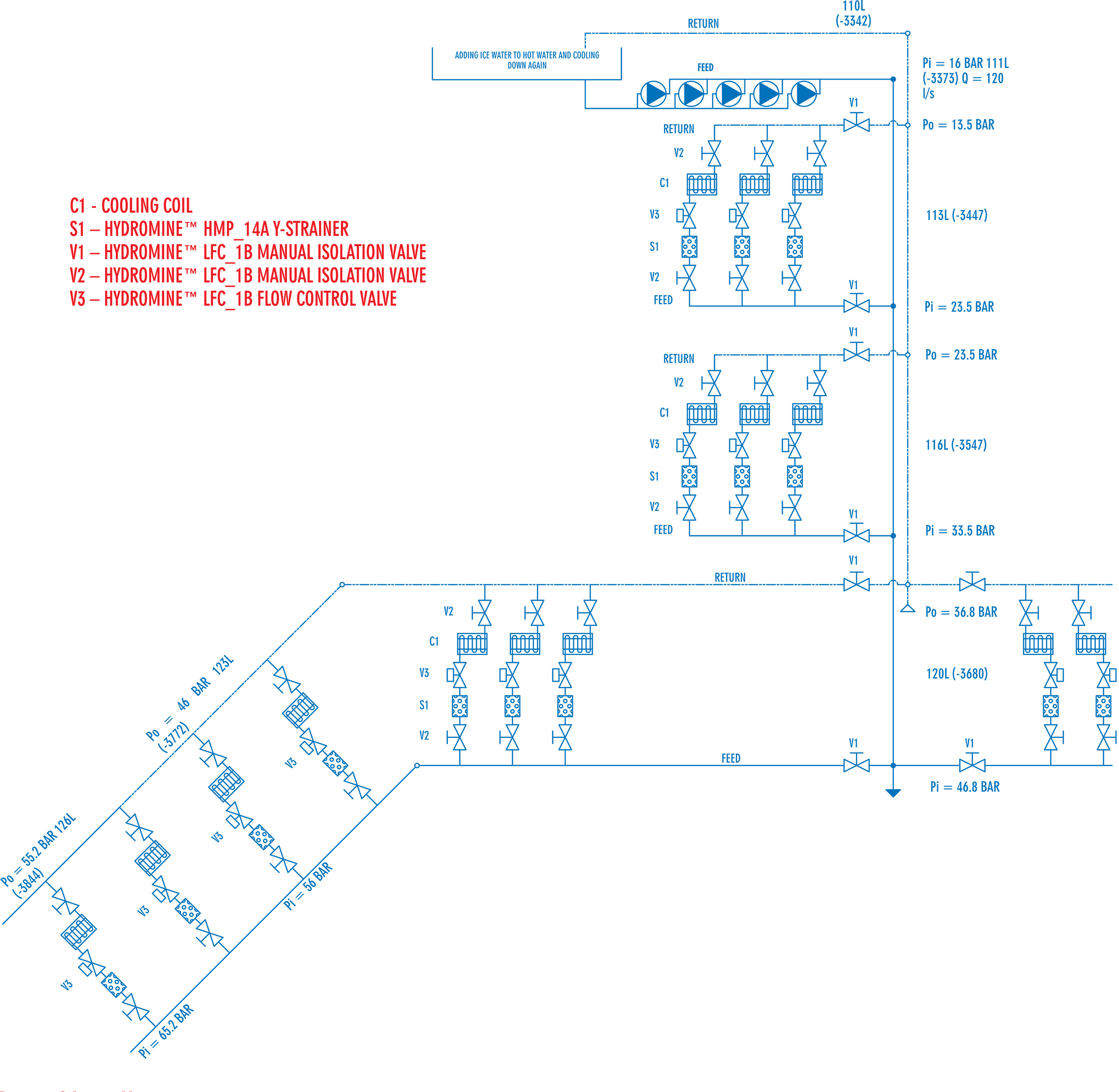
The HYDROMINE™ LFC_1B flow control valve system is a solution designed to manage the flow of fluid over the cooling coils of a closed loop cooling system that utilizes bulk air or mobile cooling coils, generally found in mine water reticulation systems. Its purpose is to maintain a consistent flow rate of the fluid, irrespective of any change that may occur in upstream pressure, or change to the demand of flow within the cooling system.
The flow control system is self adjusting, therefore, in a system that utilizes mobile cooling coils, coils can be added to or removed from the system as required, and the flow control system will adjust to the required flow rate according to the number of cooling coils present in the system.
When no flow control system is in place, the flow of the medium within the cooling coils can increase when upstream pressure rises or decrease when it drops, causing inefficient operation of the cooling coils. The use of an HYDROMINE™ LFC_1B flow control valve system will provide a consistent flow of fluid, which will cause the cooling coils to function correctly, thus providing optimum performance and The HYDROMINE™ LFC_1B flow control valve system is developed to provide a robust solution to high pressure fluid management of up to 25 MPa (3 626 psi) that is simple to implement and cost effective.
OPERATING CONDITIONS
The HYDROMINE™ LFC_1B flow control valve system is designed to operate in applications with relatively clean mediums like water and other fluids that contain low percentages of suspended solids and chlorides. It is designed to operate optimally between a pH range of 2 -14 pH.
DESIGN PHILOSOPHY
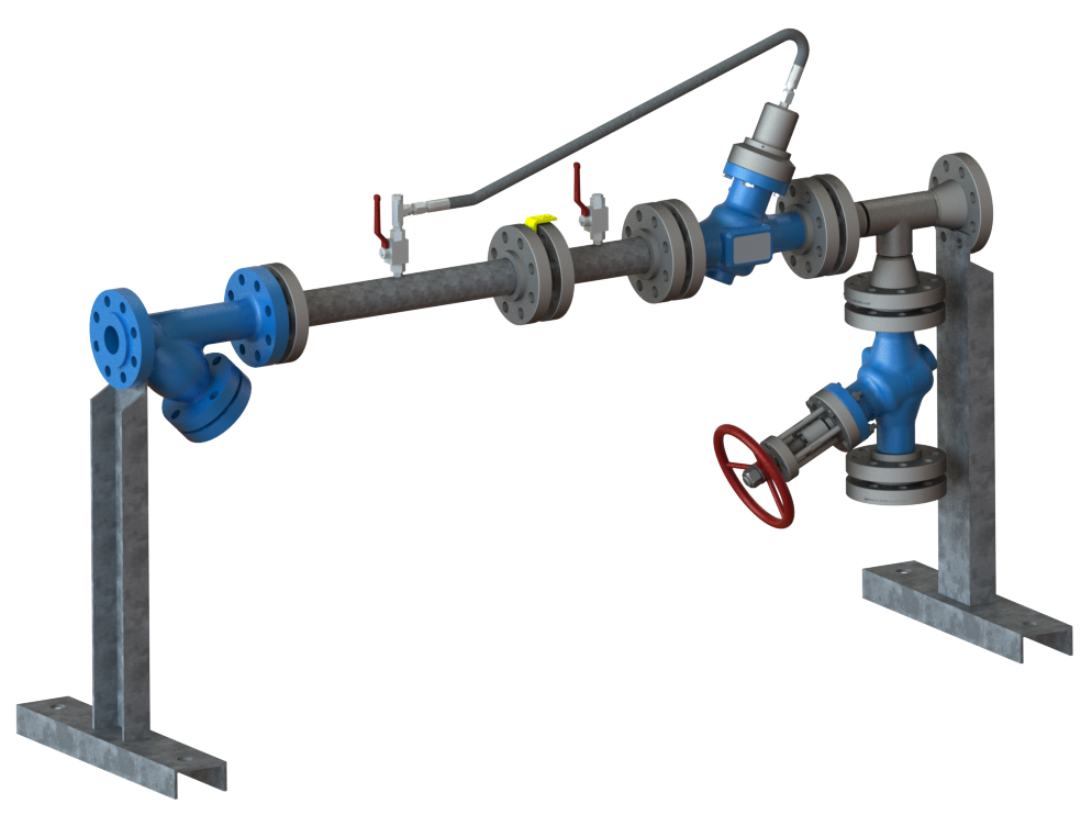
The philosophy behind the development of the HYDROMINE™ LFC_1B flow control valve was to provide a simple to use product for the end user, that has low maintenance requirements. With this in mind, it was designed to operate with only one moving arrangement, the "plug assembly". The plug assembly is a specially designed piston that is engineered to operate in an unbalanced state, to create specific conditions in the system that can be achieved without the use of a pilot or other external controllers, by means of using only inline fluid pressure as a water hydraulic force. The ratio of fixed reduction in the flow control valve is established by the ratio of its surface area that is exposed to the upstream differential pressures (dP). In the flow control application, the upstream (Pu1) and downstream (Pu2) pressures are sensed through a specially calculated orifice that is placed in the upstream (Pu1) position, before the flow control valve. The upstream (Pu1) actuates the closure of the valve, while the upstream (Pu2) actuates the opening of the valve. As the upstream (Pu1) increases in pressure, the closing force increases proportionally causing the valve to close. As the upstream (Pu1) reduces in pressure, the closing force is also reduced, and the upstream (Pu2) pressure will force the valve to open proportionally in an effort to maintain its hydraulic ratio.
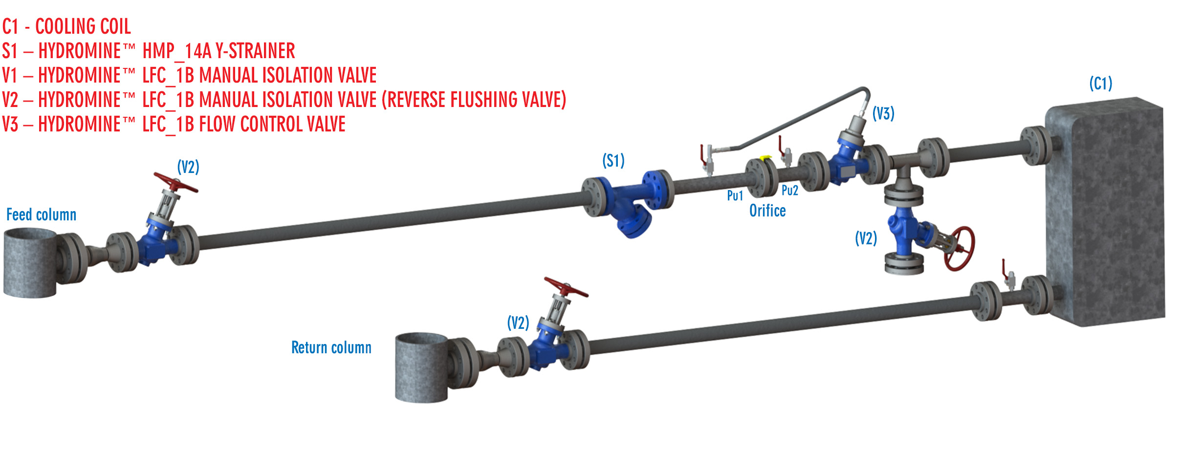
TYPICAL CLOSED LOOP COOLING SYSTEM INSTALLATION IN AN UNDERGROUND MINE
EASE OF INSTALLATION
The HYDROMINE™ LFC_1B flow control system is designed for easy installation, with little to no risk of incorrectly installing the system.
MAINTENANCE REQUIREMENTS
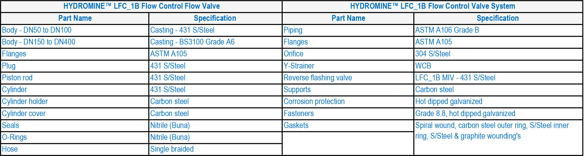
The HYDROMINE™ LFC_1B flow control system is equipped with an HYDROMINE™ HMP_14A Y-Strainer and an HYDROMINE™ LFC_1B reverse flushing valve. It is recommended that a maintenance schedule is established to regularly clean the strainer and reverse flash the coil. The HYDROMINE™ LFC_1B flow control valve requires minimal maintenance, the majority of which can be carried out on-site with the valve in situ. All of the moving parts of the flow control valve are manufactured from stainless steel, which increases their reliability and longevity.
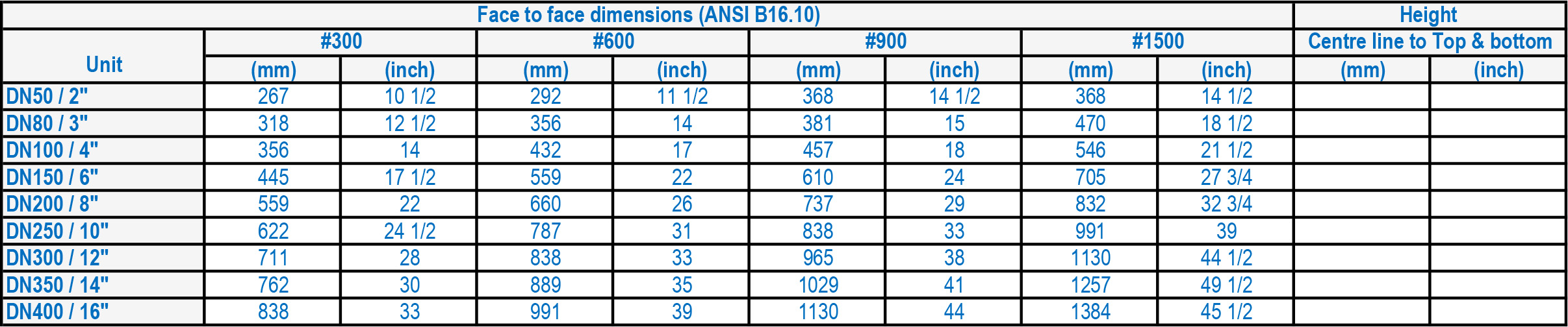
LFC™_1B VALVE DIMENSIONS
PRESSURE MEASURING POINTS AND RISK ASSESSMENT
The HYDROMINE™ LFC_1B flow control system is equipped with multiple pressure measuring points which are closed off with high pressure plugs, and a blank flange is installed on the reverse flushing valve. This is to prevent any personnel from potential hazards and possible risk of injury. During maintenance, the cooling coils and flow control system should be checked by installing pressure gauges to ensure the coil is still operating efficiently.
MATERIALS OF CONSTRUCTION
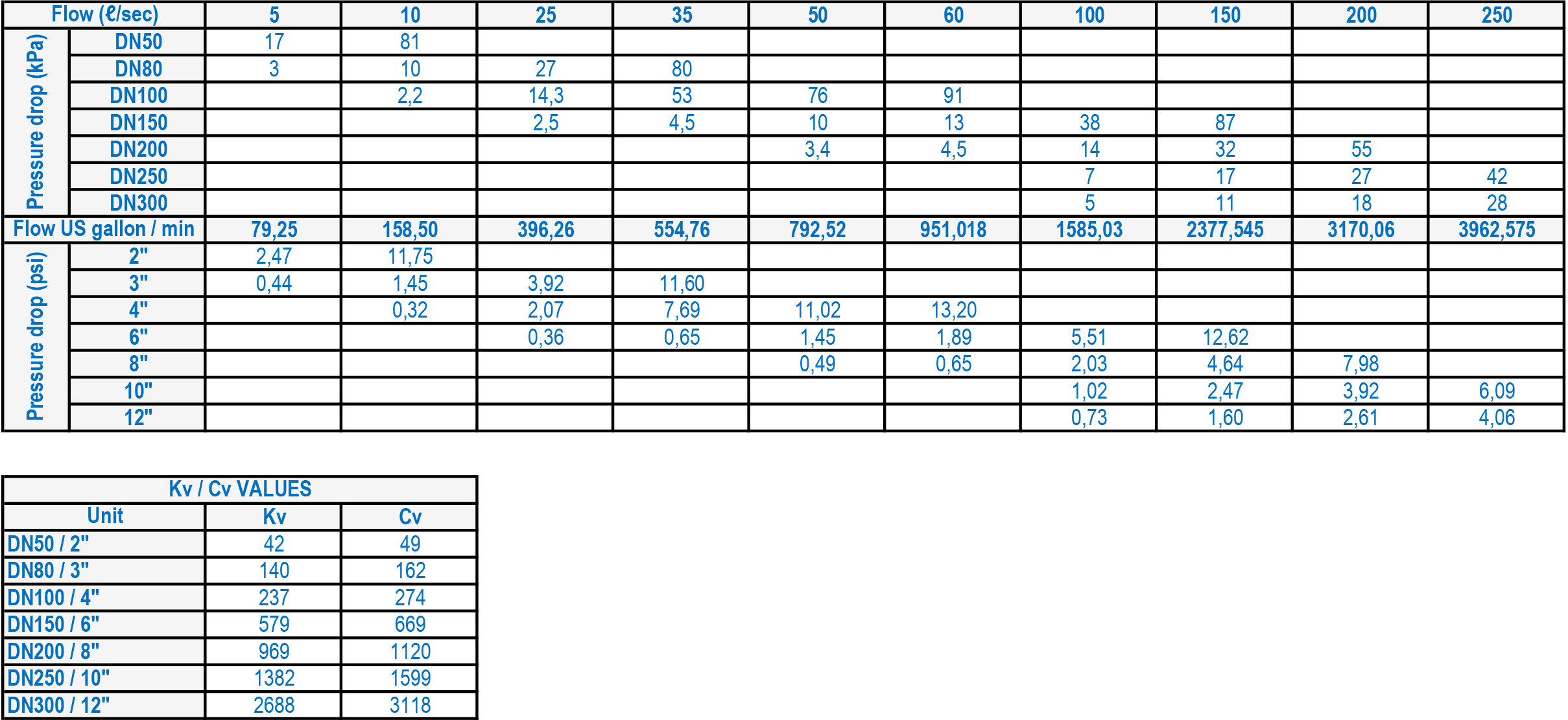
FLOW RATES
DESIGN AND MANUFACTURING STANDARDS
The HYDROMINE™ LFC_1B flow control system has been designed in accordance with various international standards as set out below:
ASME Boilers and pressure vessels design code.
ANSI B16.10 API 598
ANSI B16.34 ANSI B16.37
ANSI B16.5 ANSI N278.1
Available sizes: DN50 / 2" to DN400 / 16"
Pressure rating: up to 25MPa / 3 626 psi
Face to face dimensions: ANSI B16.10
Available end connections: ANSI B16.5, BS4504, BS10, AS/NZS 4331.1 (ISO 7005-1) DIN, All makes of grooved or ring joint couplings, HYDROMINE™ HMP U-Coupling, HYDROMINE™ HMP -TE tapered couplings and other as per clients requirement.
DOWNLOADS


